
 IEEE
IEEE Web of Science
Conditional Graph
In addition to deterministic transitions, nodes and states in LangGraph can also
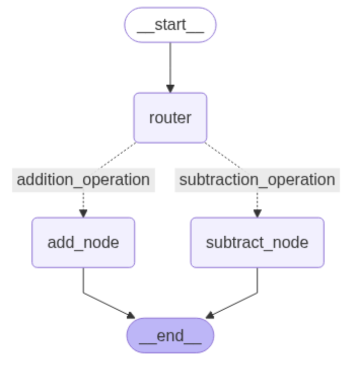
involve conditional transitions. Figure 1 illustrates
the overall flow of a conditional graph in LangGraph, which consists of a start state,
three nodes (router, add_node, and subtract_node), and an end state. The start state
is connected to the router via a directed edge (transition). The router, in turn,
connects to the add_node and subtract_node through conditional edges based on specific
criteria. Finally, both add_node and subtract_node are connected to the end state via
directed edges [1].
The primary objective is to incorporate conditional logic into the nodes of the graph. To achieve this, we define a scenario in which the graph receives an input state containing two numbers and an operation, and determines whether to compute their sum or difference based on the specified operation. The router node processes the input and makes the decision accordingly. Before implementing this logic, we first define a shared data structure to maintain the application's state during execution. This structure, called AgentState, is responsible for recording and managing the system’s state [1].

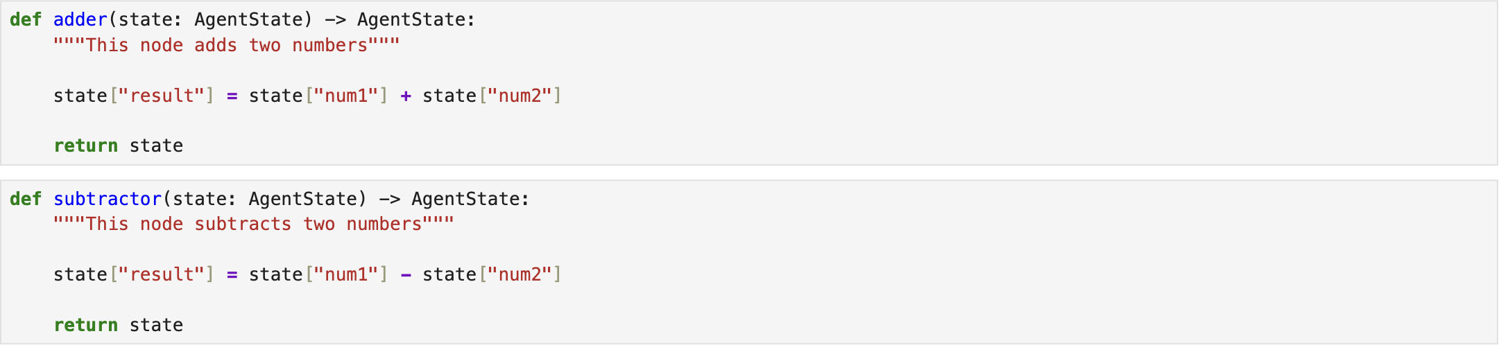
Next, all three nodes are defined. The adder and subtractor nodes correspond to add_node and subtract_node, respectively. The adder node computes the sum of the two numbers, whereas the subtractor node calculates their difference [1].
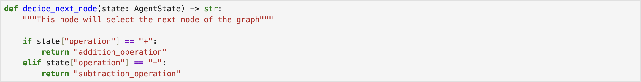
Then, the router node is defined as a function that receives the two numbers and the specified operation as inputs and determines whether to route the flow to add_node or subtract_node based on the operation type. The function then returns the updated state [1].
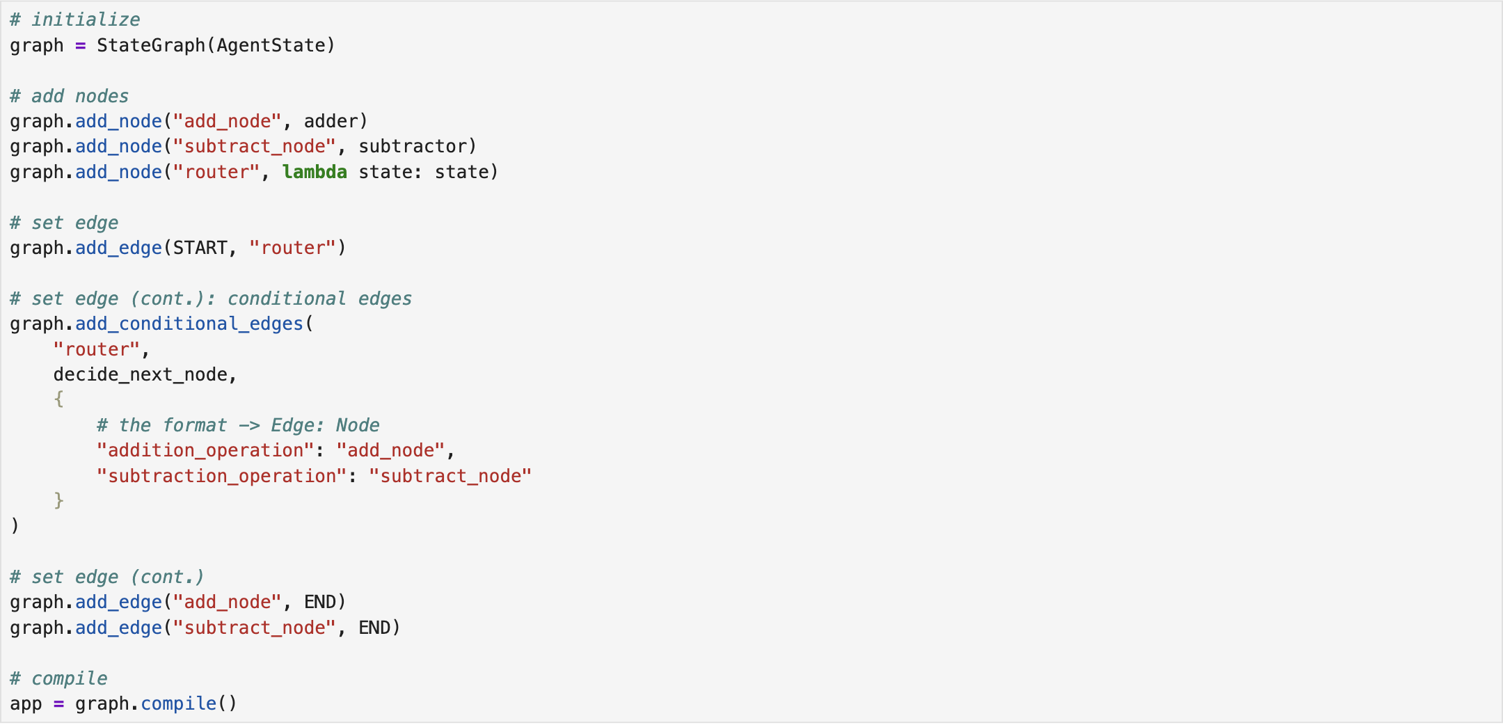
The next step involves constructing the graph. To begin, we initialize an empty graph in LangGraph, specifying its input type as state (AgentState). We then add all three nodes, i.e., router, add_node, and subtract_node, to the graph. The router is connected to the start state via a deterministic edges. Accordingly, two conditional edges are defined to connect the router to the add_node and subtract_node. Finally, both add_node and subtract_node are connected to the end state through deterministic edges. Then, we compile the graph and store it in a variable for subsequent execution [1].
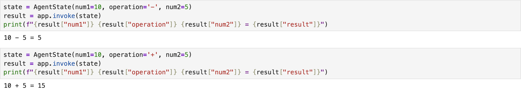
Lastly, we invoke the compiled graph by passing two example input states to that, each including two numbers and an operation. The results indicate that the designed graph-based system could successfully meet the intended objective [1]. The complete implementation script is available on Conditional Graph.
References
[1] freeCodeCamp.org, https://youtu.be/jGg_1h0qzaM?si=69DsFmR2TMN259HC.